Remote Cellular Switch: Difference between revisions
No edit summary |
No edit summary |
||
| Line 1: | Line 1: | ||
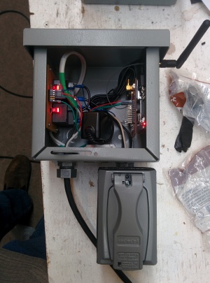
[[File:IMG_20141220_223812.jpg|thumb|DIY GSM Remote Switch]]My airplane is equipped with an oil sump heater which can be turned on an hour or so before flight to warm up the oil, leading to quicker lubrication at startup and hence less engine wear. Leaving it on 24/7 doesn't seem to be a good idea though, so there is the problem of getting it turned on before flight long enough to warm things up. That's what this little gadget is for. By sending an SMS to its phone number, the preheater can be turned on for a specified amount of time or at some point in the future. | [[Category: Airplane]] | ||
==Overview== | |||
[[File:IMG_20141220_223812.jpg|thumb|DIY GSM Remote Switch]] | |||
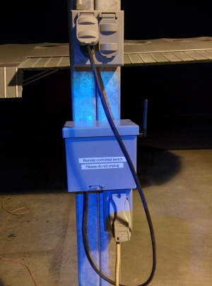
[[File:IMG_20141221_192921.jpg|thumb|Plugged in and ready to go...]]My airplane is equipped with an oil sump heater which can be turned on an hour or so before flight to warm up the oil, leading to quicker lubrication at startup and hence less engine wear. Leaving it on 24/7 doesn't seem to be a good idea though, so there is the problem of getting it turned on before flight long enough to warm things up. That's what this little gadget is for. By sending an SMS to its phone number, the preheater can be turned on for a specified amount of time or at some point in the future. | |||
The following commands are supported: | |||
* On switchID [time] duration | * On switchID [time] duration | ||
| Line 9: | Line 10: | ||
Currently there are two switchIDs, 1 and 2. Duration is in minutes and the time format is hh:mm. Use 24hr time. If no time is specified the switch turns on immediately. If no switch ID is specified in the 'off' command, all switches get turned off. | Currently there are two switchIDs, 1 and 2. Duration is in minutes and the time format is hh:mm. Use 24hr time. If no time is specified the switch turns on immediately. If no switch ID is specified in the 'off' command, all switches get turned off. | ||
==Hardware== | |||
I based this on a raspberry PI. They have plenty of GPIO and a 3.3v level RS-232 port which is perfect for communicating with most of the GSM modem chips out there. After I started I found this little guy which plugs right into a raspberry PI no extra wiring necessary: http://imall.iteadstudio.com/raspberry-pi-gsm-add-on.html Some of the unused GPIO pins are brought out on that SIM900 breakout board so use ones that are convenient to get ahold of to plug the relays into. | |||
The SIM900 has a pretty simple interface using the standard 'AT' commands. I wrote a pretty short Python program to set the SIM900 up and then react to the messages. The best way I found to do it is put the module in a sort of 'asynchronous' mode so incoming text messages are output as soon as they come in. It replies to valid commands with a confirmation message. | |||
Each of the two [http://www.newark.com/webapp/wcs/stores/servlet/ProductDisplay?catalogId=15003&langId=-1&urlRequestType=Base&partNumber=66F6687&storeId=10194 relays] can handle up to 30 amps and have 5v 200mA coils. To drive them I used 2n2222 transistors driven directly by the pi's 3.3v GPIO outputs with a 500 ohm resistor in series. This should only draw a few mA from the GPIO and gets the transistor into saturation. Put diodes backward across the coils to protect the transistors from voltage spikes when the relays turn off. | |||
==Software== | |||
The python software is on github at the following link: | |||
https://github.com/AD7ZJ/GsmSwitch | |||
Put it wherever you like on the PI's filesystem, and then add a line to /etc/rc.local. Use the absolute path to the python script and be sure to put an & symbol afterwards so the rest of the boot process can proceed - the python script runs forever and never returns. | |||
Revision as of 07:48, 30 December 2014
Overview


My airplane is equipped with an oil sump heater which can be turned on an hour or so before flight to warm up the oil, leading to quicker lubrication at startup and hence less engine wear. Leaving it on 24/7 doesn't seem to be a good idea though, so there is the problem of getting it turned on before flight long enough to warm things up. That's what this little gadget is for. By sending an SMS to its phone number, the preheater can be turned on for a specified amount of time or at some point in the future.
The following commands are supported:
- On switchID [time] duration
- Off [switchID]
Currently there are two switchIDs, 1 and 2. Duration is in minutes and the time format is hh:mm. Use 24hr time. If no time is specified the switch turns on immediately. If no switch ID is specified in the 'off' command, all switches get turned off.
Hardware
I based this on a raspberry PI. They have plenty of GPIO and a 3.3v level RS-232 port which is perfect for communicating with most of the GSM modem chips out there. After I started I found this little guy which plugs right into a raspberry PI no extra wiring necessary: http://imall.iteadstudio.com/raspberry-pi-gsm-add-on.html Some of the unused GPIO pins are brought out on that SIM900 breakout board so use ones that are convenient to get ahold of to plug the relays into.
The SIM900 has a pretty simple interface using the standard 'AT' commands. I wrote a pretty short Python program to set the SIM900 up and then react to the messages. The best way I found to do it is put the module in a sort of 'asynchronous' mode so incoming text messages are output as soon as they come in. It replies to valid commands with a confirmation message.
Each of the two relays can handle up to 30 amps and have 5v 200mA coils. To drive them I used 2n2222 transistors driven directly by the pi's 3.3v GPIO outputs with a 500 ohm resistor in series. This should only draw a few mA from the GPIO and gets the transistor into saturation. Put diodes backward across the coils to protect the transistors from voltage spikes when the relays turn off.
Software
The python software is on github at the following link: https://github.com/AD7ZJ/GsmSwitch Put it wherever you like on the PI's filesystem, and then add a line to /etc/rc.local. Use the absolute path to the python script and be sure to put an & symbol afterwards so the rest of the boot process can proceed - the python script runs forever and never returns.