KD7LMO Home PageNear Space Return VehiclePayloadsGround StationTechnologyArizona Near Space ResearchContact

Ground Station

IRLP

Mobile GPS

ATV Receiver

Overview

Block Diagram

Controller

Mechanical

Antenna/LNA

Source Code

GNU Radio
LED Clock
LED Clock
LED Clock
Nixie Clock
LED Clock
AM Tube Radio
LED Clock
FM Tube Radio
LED Clock
Tube Amplifier

Overview

Shown below is battery powered, portable S-Band (2.4 GHz) FM video receiver using LCD display technology.  The light weight, portable package includes the receiver, power for a feed line driven LNA (Low Noise Amplifier), controller, and user interface.  The user interface consists of a two line LCD display and three push buttons.  The LCD typically displays the operational frequency and signal strength.  The push buttons are used to select the receive frequency as well as adjust the video LCD brightness, contrast, chroma level (color), phase (tint), back light brightness, and 4:3 or 16:9 video mode.


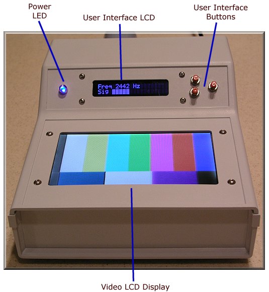
Portable ATV Receiver


The rear panel includes the following ports and switches.
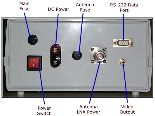
DC Power Plug  Operates over the standard automotive voltage range of 10 - 18 VDC.  The receiver is protected against reverse polarity and transient spikes common in the automotive/mobile environment.

Main/Antenna Fuse  Provides protection from overload or a shorted antenna connection as well as equipment failure.

Antenna  The N type antenna connector provides a rugged RF input connection as well as DC voltage for an antenna mounted LNA.

RS-232 Data Port  Provides signal strength indication for automatic tracking applications.  The embedded firmware may be modified to support other features such as automatic antenna pointing, VCR control, or data logging.

Video Output  The video signal on the LCD display is also routed to a rear panel connector for recording with a standard VCR or digital recorder.


Rear Panel
 

Copyright © 2001-2009, KD7LMO

Web space provided by ESS, Inc. for all your consulting needs.