KD7LMO Home PageNear Space Return VehiclePayloadsGround StationArizona Near Space ResearchContact

Overview

PCB

PIC Programmer

Power Converter

Power Sources

The Shack

Tips/Techniques

Vendors

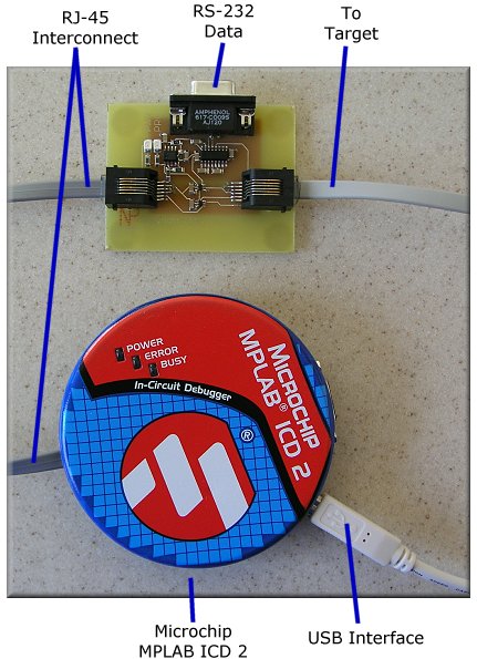
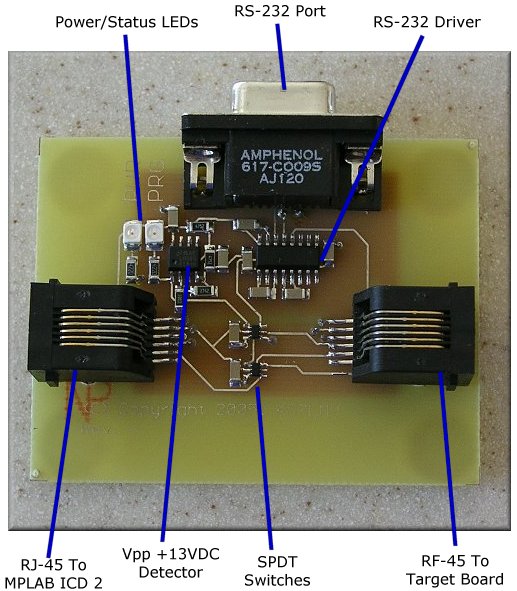
PIC Programmer

The Microchip MPLAB ICD 2 is the latest development tool for use with PIC processors that have an ICSP (In-Circuit Serial Programming) port.  The ICSP is a simple two wire interface that allows the developer to erase, program, and debug the processor.  The ICD 2 is an updated device that is controlled through the USB port.  Although the ICD 2 makes programming and development easy, it doesn't provide the capability to communicate with the PIC processor once it is operational.  Communicating with the operational device might be useful for setting a configuration, an engineering or debug mode, or downloading a device log.  With the PIC programmer interface shown below, the same control pins used for programming and debugging are automatically switched to a standard RS-232 port.

The interface is supported through simple application commands.  The following code snippets show the configuration of the port, writing text and data, and reading users commands.
 
// Configure the ICD pins for use as an RS-232 control port.
#use rs232(baud=57600, xmit=PIN_B7, rcv=PIN_B6, STREAM=PC_HOST)

// Simple user interface menu.
fprintf (PC_HOST, "Menu: (E)rase Flash, (R)ead Flash, e(x)it debug mode?\n\r");

// Sending data to to the host.
fprintf (PC_HOST, "%02x", buffer[i]);

 // Reading commands from the host.
command = fgetc(PC_HOST);


Shown below is the hardware setup of the device.  Rather than connecting the ICD 2 directly to the target, it passes through the interface board.  The interface board detects when the ICD 2 is active and automatically switches the ICD pins to the ICD 2.  Once the device has been programmed, the pins are switched to the RS-232 driver.


System Configuration.


Shown below is the interface board.  The board is populated with RJ-45 connectors for easy connection to the MPLAB ICD2 and target boards.  The circuit is powered through the target device, or optionally through the MPLAB ICD2 for low current target devices.


MPLAB ICD2 Interface Board.


Schematic / PCB Layout


For best quality, print the schematic on a single 8½ x 11" sheet of paper in landscape mode using your favorite graphics application.

MPLAB ICD2 Interface Schematic MPLAB ICD2 Interface PCB Top Layer MPLAB ICD2 Interface PCB Bottom Layer
Schematic
(Graphic - GIF)
PCB Layout
Top Layer
(Adobe PDF)
PCB Layout
Bottom Layer
(Adobe PDF)


Additional information on viewing the PCB artwork, PCB tools, and component libraries is available in the Technology section.


Copyright © 2001-2009, KD7LMO

Web space provided by ESS, Inc. for all your consulting needs.