FLARM Teardown
FLARM teardown
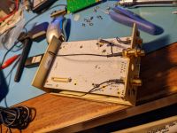
FLARM is pretty popular in the sailplane crowd for collision avoidance. It's a nice system although pretty expensive. It communicates your current location and trajectory to other systems on the 915 MHz ISM band. I was installing a PowerFLARM core in a glider and unfortunately got pin 7 and 8 mixed up on the DB9 connector, applying 12v to the 5v output instead of the 12v input. Not the best design putting those two pins right next to each other... Took it apart to see if it could be easily repaired, it looked like a couple regulators had been taken out and no power was getting to the processor board. I didn't have the right regulators on hand and too many other projects at the time to go further, so I just sent it in for repair.
It ended up requiring both the boards to be replaced. My mistake, but I do think it's kind of unfortunate such an expensive device doesn't have better input protection. I was also disappointed to learn that the stock PowerFLARM does not receive 978 UAT ADSB - only 1090. The hardware is present but it costs another $200 to enable in software.


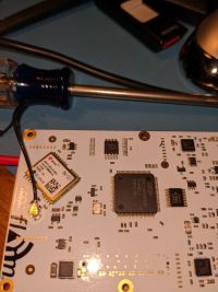
Processor board
- Processor is an LPC2387.
- NRF905 transceivers perform the RF communication.
- SST 25VF0328 flash chip, probably for storing the flight log.
- uBlox NEO-6Q-0-001 GPS
Power supply board
- Linear Tech LTM8032 switching PS module, reduces the input voltage to 5v.
- LMZ10503 switching module to reduce 5v to 3.5 (IIRC)
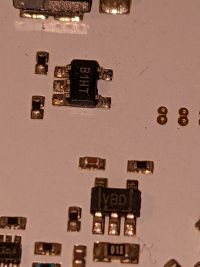
- A handful of small TPS793 LDOs to reduce the 3.5 to other voltages.
- Some kind of barometric pressure sensor
