Fixing a Stratus 1

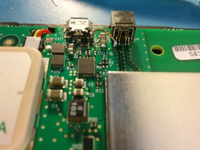
A friend had a first generation stratus that the USB connector broke off of, which is a pretty big problem beings that is how the battery is charged. Fortunately he still had the connector, which was a surface mount design. The pads had pretty cleanly pulled off the board, so I carefully bent them back into the correct positions and then glued them back to the PCB using CA glue. Several iterations were necessary to get an exact fit - I wanted everything to line up exactly so the traces would be easy to reconnect. As you can see in the pictures, the pads which connect to power, gnd, d+ and d- are sort of tucked underneath the connector making the soldering quite tricky. Connecting power and ground were pretty easy but the data lines were harder to get right.

It was during this experimentation I connected a charger and noticed something surprising - the external power LED was blinking red, which according to the manual indicates "Incompatible charger or charger is unable to provide sufficient power". Funny, this was a 2A charger I often use for charging my phone. Hooking it up to a lab power supply indicated it was drawing 480 mA - well within the range of most USB chargers. Monitoring the battery voltage confirmed it was indeed charging, but the LED continued flashing red. I then suspicioned that the data lines were not connected, and Appareo was doing something a little "non-traditional" with them to detect their proprietary charger! Some more time spent with my finest soldering iron and an ohm meter rewarded with a solid connection to both data lines, and suddenly the external power LED turns yellow while charging - only when using Appareo's charger, mind you! This is the sort of thing that irritates me with the "Apple crowd". There's no good reason to build such a feature into the product except to rip the customer off by selling expensive chargers. Oh well, at least they used a micro USB and not a proprietary connector too...
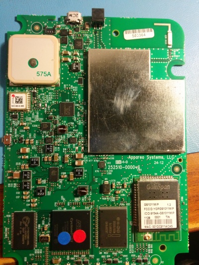
A uBlox MAX-6G GPS chip provides the device's current location and a Cypress CY8C32 SOC is the on board microcontroller. That's an 8051 core with a bunch of peripherals. The RF chain to receive the 978 MHz UAT link seems to be hidden under the metal can, but an Altera FPGA is visible probably for demodulating the baseband signal. The other large metal module in the lower right is the WiFi adapter that provides connectivity for foreflight.