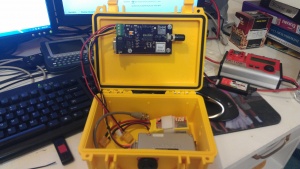
PIC APRS Beacon

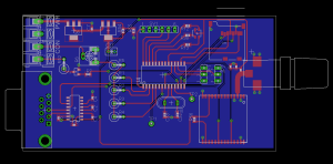
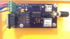
This project was started as a fun experiment to see if an AFSK signal could be generated using only an 8 bit PIC and a resistor ladder network. Once that was working, I laid out a board for it and added the additional software logic to get what you see here.
Overview


- Simple and inexpensive APRS beacon
- AFSK is generated using a resistor network so no modem chip is needed
- Adjustable audio output allows interfacing with a variety of radios
- Integrated GPS with helical antenna - no cables to break and works in any orientation
- NMEA strings are stored on a FAT32 formatted micro SD card
- Software is modular and easy to understand
Hardware
The hardware started out based around a PIC18F14K22 which is one of the higher end 8 bit PICs. It's capable of running at up to 64 MHz, or 16 MIPs since each instruction takes 4 clock cycles to execute. This worked well, but only had 512 bytes of RAM which wasn't enough for handling NMEA strings and a full FAT filesystem. I switched to the PIC18F2525 since it has plenty of both codespace and RAM. It's running at 32 MHz clocked off the internal oscillator, although the current board layout has provision for an external crystal should that prove to be necessary for temperature stability.
For communication it's currently using a VHF Maxon Radio. These can be tuned from 144 to 178 MHz and are very durable - the downside is their weight (about 9oz).
An onboard Trimble Copernicus provides GPS data. I wanted to try a helical GPS antenna instead of the patch antennas we've used in the past since those tend to lose lock if the payload somehow gets flipped over. This antenna is soldered directly onto the board so there are no cables to break.
Software
The source code is hosted at github here https://github.com/AD7ZJ/PICAprs
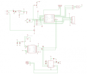
The software is written in C and built using MPLab X and the XC8 compiler. The AFSK modulator uses a resistor network and a 16 entry lookup table to produce a sin wave. There's a 1k resistor, 2k, 4k, 8k (or as close as standard values allow) which let 4 digital outputs work as a primitive sort of DAC (think powers of 2). The lookup table is designed to approximate a sin wave using the 16 possible outputs of this DAC. The sin wave's frequency can be adjusted by how quickly we step through the table. This timing is set by one of the PIC's internal timer modules, Timer2. I initially tried to use this on an interrupt routine, but it turned out the context switch time to service each interrupt was taking too long. So while a packet is being sent, nothing else is happening.
AFSK switches between 1200 Hz and 2200 Hz to represent mark and space, with a baud rate of 1200 bps. The data itself is encoded using NRZI (non-return to zero inverted), meaning zeros cause a state (as in, mark or space) change while 1's cause the state to remain the same. Bitstuffing is performed to keep 5 or more 1's from ever being sent in a row - this helps keep the receiver's clock synced up.
NMEA data from the GPS is placed in a FIFO by the interrupt handler and then removed from the FIFO and parsed by the background task. At the same time, the strings are written to the filesystem on the SD card. The CHaN FAT filesystem implementation is used because it's lightweight and designed to fit in the limited space of a micro controller. The SD card itself interfaces with the PIC via the SPI interface.
The packets themselves use the MIC-E compressed format which has the advantage of being transmitted quickly and contains all the necessary info in a single packet.
Currently the remaining capabilities still need to be implemented:
- Configurable callsign and digi paths