Single Digit IN-18 Nixie Clock
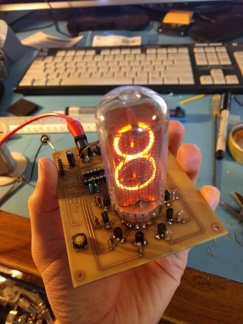
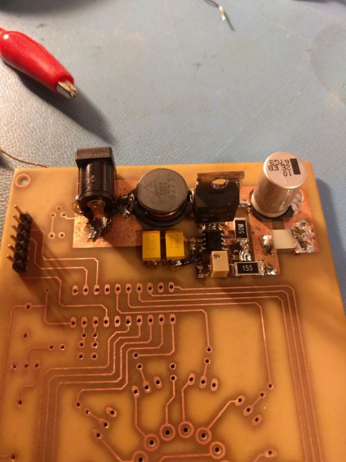
I think nixie tubes are pretty cool, and the IN-18 is one of the larger tubes out there. They are fairly expensive being somewhat rare, so I decided a clock using only one of them is sufficient! I drew up the schematic and laid out the board using Eagle, then printed it out on magazine paper to do the "toner transfer" method of etching. The circuit is quite simple, using a PIC16F690 to drive the digits and a small boost converter to boost the incoming 12v to ~170v.
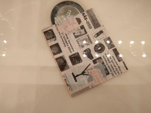
I draw the circuit out in Eagle, route the board, and then print it on magazine paper with a laser printer. I rough up the copperclad with a scotchbrite pad and then get it nice and clean. Getting the top and bottom layer to line up adds an additional challenge. The way I did this was was to tape the top and bottom layers together on one end, such that they're lined up perfectly. You can shine a bright light from behind to see when the vias line up. Now lay the printout on the board and iron it on, then toss it into water.
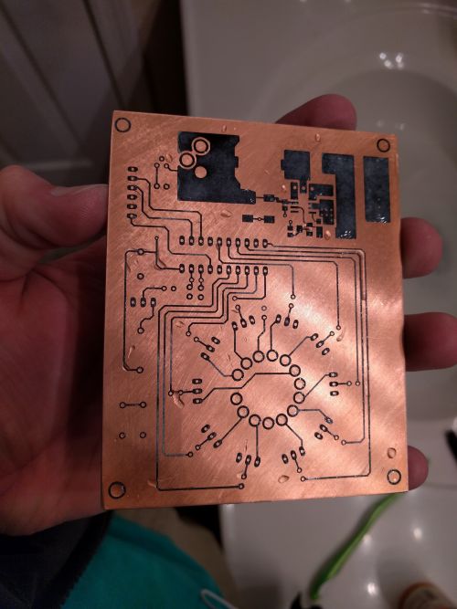
Once the paper is good and soggy, gently pull it off and the toner should be left behind, stuck to the copper.
Hopefully it looks like this!
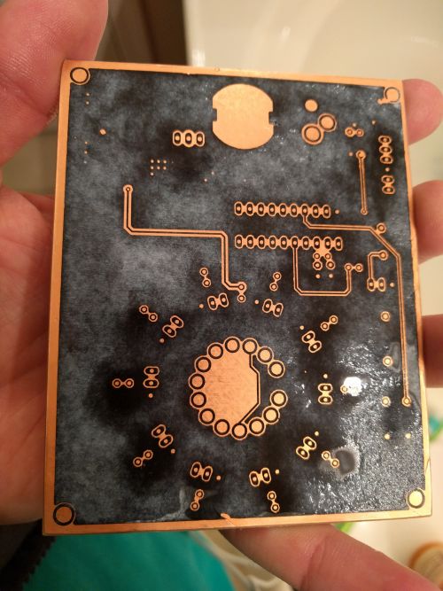
Here's the bottom.
After etching I drilled all the holes. Here it is being soldered together. I got some socket pins that fit the nixie tube so the nixie doesn't have to be directly soldered to. The software is written in C and built using the microchip free XC8 compiler. The PIC uses a 32.768 kHz crystal for the clock. This works pretty well but it gains a minute every so often. The caps balancing the crystal might need tweaking a little bit.
I have the source files in a git repo: https://github.com/AD7ZJ/NixieClock
