|
|
Hardware
The first prototype build has been completed and tested. The radio needs tuning in all the RF and IF stages, but I was able to pick up a couple stations at the high end of the AM band. The LO vs. tuned RF stage tracking is a mess right now.
The only white wire change to the PCB was in the frequency counter section. During the initial design, I was not sure where to measure the LO frequency. There were three possible points; the grid, the cathode, or the plate. After building the prototype, I used an oscilloscope to measure the voltage levels and view the waveform at each point. The grid was a very a very clean 75V P-P sine wave. However, it was very sensitive to even the 1M scope probe and would change the LO frequency because of loading. The cathode was a ratty clipped sine wave at 18V P-P. The plate of course has the B+ 180VDC sitting on it. Even with a power transformer, I still wanted to isolate the low voltage 3.3VDC section from the 180VDC B+. If a coupling capacitor breaks down, I get the full 180VDC on the 3.3VDC supply which may also be connected through the USB port to a computer. Probably resulting in the destruction of something.
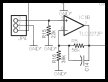
The solution was easy actually, I connected the unused oscillator transform section to a voltage divider and the high speed comparator. Even the transformer coupling provided robust 30V P-P. To minimize the loading effect on the oscillator, it was coupled thorough a a high impedance 470K resistive divider. Since the waveform has a -15 VAC component, a high speed Schottky diode was used to clip the negative signal to ground after the voltage divider. With the diode, there is a small -250mV excursion, but it is well within the specified limits of the comparator operating in single supply mode. Since the late 1980s, very few op-amp and comparator circuits require a ± voltage rail. Modern components are designed to operate with a single supply rail and within a hundred millivolts of each rail.
The frequency is measured and displayed on the Nixie Tube display every 100mS against the ±1.5 PPM 10MHz TCXO. It will make tuning and aligning the LO stages much easier.
Note, the schematic and PCB layout below have been updated to reflect this change.
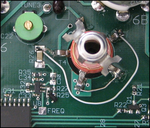
LO Frequency measurement detail.
Bill of Materials
For following is the Bill Of Materials that provides quantity, value, device type, reference designation, vendor, vendor part number, and description. There should be enough information to order the components.
PCB
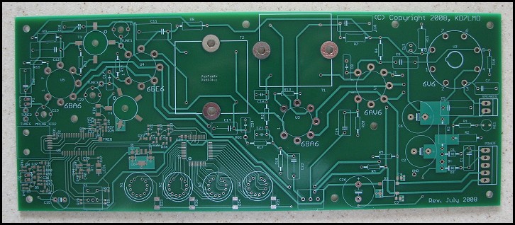
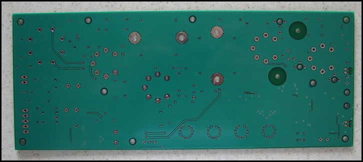
Shown below are the front and back of the fabricated PCB (Print Circuit Board). Although the same layout is provided in PDF files, the green boards always look nice. Note the full ground plane on the rear of the PCB.
Schematic / PCB Layout
For best quality, print the schematic on a single 8½ x 11" sheet of
paper in landscape mode using your favorite graphics application.
 |
 |
|
|
 |
|
|
Gerber Files
PCB Fab
(ZIP File) |
Schematic
Page 1
(Graphic - GIF) |
Schematic
Page 2
(Graphic - GIF) |
|
PCB
Layout
Top Layer
(Adobe PDF) |
PCB
Layout
Bottom Layer
(Adobe PDF) |
PCB
Parts Layout
(Adobe PDF) |
Additional information on viewing the PCB artwork, PCB tools, and
component libraries is available in the Technology section. |