|
|
Hardware
Shown below, is a top view of the Nixie Tube Clock PCB. The PCB contains the GPS engine, embedded controller, switching power supplies, as well as sockets for the Nixie Tubes. The PCB is self contained and only requires DC power and a GPS antenna connection for a fully function clock. There is an optional dry-relay input on the power connector for an external mode switch or a motion sensor to turn the clock off when no one is around to extend tube life.
The major sections include -
 GPS Receiver A low cost Trimble Resolution-T GPS receiver provides time of day as well as date. You'll never have to set your clock and it will automatically adjust for the local time based on your location. GPS Receiver A low cost Trimble Resolution-T GPS receiver provides time of day as well as date. You'll never have to set your clock and it will automatically adjust for the local time based on your location.
Programming Port An RG45 connector (LAN cable) that connects directly with the Micro Chip MPLAB ICD2 programmer. With the ICD2 you don't need any additional programming hardware. The ICD2 connects to a PC through USB for programming and debugging.
Embedded Controller A Microchip flash based PIC 18LF2525 embedded controller. An Orange Vishay LED (TLMO3100) is used for a status LED as well as power supply indicator. The orange color is very close in color to the Neon Bulbs and Nixie Tubes.
Switching Power Supplies Two switching supplies generate +3.3 VDC for the embedded controller and GPS engine and +190VDC for the Nixie tubes from an unregulated 10-18VDC "wall wart" type power adapter. The PCB layout of the National LM2762 +3.3VDC supply follows the application notes. The PCB layout of the Maxim IC MAX1771 follows standard practices with a large ground planes and short PCB traces. Both switching supplies operate near 90% efficiency.
High Voltage Tube Driver A pair of Supertex HV5522 provide 32 high voltage, open drain outputs to control the Nixie Tube segments. The HV5522 are chained together
Neon Bulb A pair of standard NE-2 Neon Bulbs provide "colons" to separate the hours, minutes, and seconds displays. The bulbs are soured through 270K resistors to limit the bulbs to 500uA of current.
Nixie Tubes The Nixie Tubes electrically appear like a high voltage regulator. Depending on the digit selected, they regulate at 135-145VDC. For best life and brightness, the tubes need to sink around 5mA. Therefore a the HV supply voltage is set at +190VDC. With the tube at 140VDC, 50 volts will drop across the 10K anode resistor causing 5mA of current to flow through the Nixie Tube (from Ohm's law, 50V / 10K = 5mA). The 5mA of current provides good brightness and tube life by limiting cathode poisoning. Cathode poisoning are small deposits (oxidation) of the cathodes that make the digits appear incomplete and may prevent it from lighting.
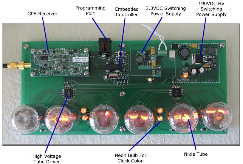
Top View of Nixie Tube Clock
Schematic / PCB Layout
For best quality, print the schematic on a single 8½ x 11" sheet of
paper in landscape mode using your favorite graphics application.
 |
|
|
 |
|
|
Schematic
Page 1
(Graphic - GIF) |
Schematic
Page 2
(Graphic - GIF) |
|
PCB
Layout
Top Layer
(Adobe PDF) |
PCB
Layout
Bottom Layer
(Adobe PDF) |
PCB
Parts Layout
(Adobe PDF) |
Additional information on viewing the PCB artwork, PCB tools, and
component libraries is available in the Technology section. |