KD7LMO Home PageNear Space Return VehicleGround StationTechnologyArizona Near Space ResearchContact

Payloads

Payload Comp

Overview

Block Diagram

Processor


GPS

TNC

Local I/O


Repeater


Diplexer

Commands

Source Code


Mechanical

Telemetry

Data Logger

Micro Beacon

Cut Down

HF-APRS

Video Link

Pico Beacon

NSRV Beacon


APRS Beacon

GPS

The heart of tracking and recovery is the GPS (Global Positioning System) receiver.  The GPS receiver provides latitude, longitude, course, speed, and altitude information to the computer.  Because of the receiver's small size and surface mount connector requirements, the module was mounted on a PC board.

Motorola Oncore M12+ receiver.  12 channel receiver optimized for fast lock after signal loss.

Active antenna is mounted on top of the aircraft.

Low power, 3.0V design.  Power converter and 3-5 volt logic translator included on daughter card.

Motherboard/GPS module weight 1.8 ounces.  Antenna/feed line 0.5 ounces.  Total GPS weight 2.3 ounces.

Smaller, all surface mount design over GPS receiver board used in Payload Computer.


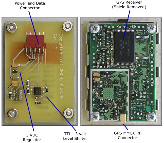
GPS receiver assembly - front/rear view.


Schematic / PCB Layout


For best quality, print the schematic on a single 8½ x 11" sheet of paper in landscape mode using your favorite graphics application.

GPS Receiver Schematic Power Convter PCB
Schematic
(Graphic - GIF)
PCB Layout
(Adobe PDF)


Additional information on viewing the PCB artwork, PCB tools, and component libraries is available in the Technology section.


Copyright © 2001-2009, KD7LMO

Web space provided by ESS, Inc. for all your consulting needs.