|
|
Hardware
Shown below is the Pico Beacon controller board. The board is a
custom built, 3" x 3½" double sided circuit board. The
board contains the processor as well as the power converter, temperature
sensor, DDS, amplifier chain, and GPS engine.
 Programming
Port In-circuit serial programming and debug port for PIC18F2525
processor. Software developed in C programming language.
Interfaces directly to Microchip's newest MPLAB ICD-2 USB based
programmer/debugger. Programming
Port In-circuit serial programming and debug port for PIC18F2525
processor. Software developed in C programming language.
Interfaces directly to Microchip's newest MPLAB ICD-2 USB based
programmer/debugger.
Flight
Data Recorder 1M x 8 bit (1,048,576 bytes) serial flash memory for flight data
recorder.
Temperature
Sensor National Semiconductor LM92 digital temperature sensor.
Power
Converter High
efficiency power converter. Heat sink not required. Provides
3.2 VDC for PA and controller. Designed to operate from 2,
1½VDC AA
Lithium batteries.
Output
Filter Traditional, 5 pole low pass filter using LC network
with surface mount capacitors and inductors.
SMA
RF Output Light-weight, compact SMA connector serves as RF output port.
RF Power
Amplifier RF Microdevices RF2192 1 watt power amplifier biased to
500mW for improved battery life and reliability. Thanks to our local
sales representative for providing sample parts and an evaluation board.
RF
Filter/Amplifier Chain A pair of band pass filters and MMIC
amplifiers provide a gain of 18 and 10dB in the transmit operational band.
DDS
(Direct Digital Synthesizer) Analog Devices AD9954 DDS generates modulated UHF carrier.
Digital modulator is multi-standard capable. Software currently
supports 1200bps A-FSK and 9600bps FSK.
19.2
MHz TCXO Temperature Compensated Crystal Oscillator services as
master clock for DDS and processor. Part rated at +/- 2.5 PPM
accuracy. Transmit frequency automatically adjusted using GPS 1-PPS.
Embedded
Controller
Microchip PIC18F2525 flash memory based processor running at 19.2MHz.

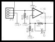
Pico Beacon board.
Schematic / PCB Layout
For best quality, print the schematic on a single 8½ x 11" sheet of
paper in landscape mode using your favorite graphics application.
NOTE: There were white wire and component value changes that are not
reflected in the schematics and board layout provided below. The
change will be incorporated into the design information as time permits.
 |
 |
|
Schematic
(Graphic - GIF) |
PCB
Layout
Top Layer
(Adobe PDF) |
PCB
Layout
Bottom Layer
(Adobe PDF) |
Additional information on viewing the PCB artwork, PCB tools, and
component libraries is available in the
Technology section.
|