

|
|
|
|
|
|
|
NSRV
- Near Space Return Vehicle Project Origin During the ANSR-3 balloon mission, the tracking and recovery teams had to travel over 90 miles (140 km) and into a mining quarry to recover the payload package. As I was making the 1½ hour trek back home, I thought there has to be a better way. About a week later, a very interesting web link was posted to our group's web page that showed another person's effort in creating an autonomous glider. His excellent work, as well as other NASA and UAV projects have served as the inspiration for this project. This NSRV project started December 1st, 2001. The project is divided into three major elements. The first is a dual control system that will be incorporated into a standard, powered R/C aircraft. Once airborne, the autonomous control system is turned on and allowed to fly the aircraft. The second is a ground station element that will process telemetry from the glider or R/C aircraft. The ground station will also control flight parameters and emergency systems. The third element is lifting a glider aloft with a balloon, releasing it, and allowing it to fly back to the starting location. There will be many challenges ahead, but nothing ever worth doing is simple or easy. Status Standard packet radio is available on 445.950 MHz when testing is in progress. All flight testing is conducted at the Scottsdale Flyers Club locate near Scottsdale Communicate College in Scottsdale, Arizona. The campus is located at Chaparral Road and the loop 101 freeway. Shown below is a picture of the R/C (Radio Control) aircraft that was used as a test platform for the control system. The large trainer aircraft is easy to fly and with its 1.9 horse power engine, can carry several pounds of payload. Traditional R/C controls are used to control the aircraft during take off and landing. Once in flight, the automated control system can be activated and tested for stability and proper operation. An over ride switch allows control to return to the R/C radio if any abnormal conditions occur. 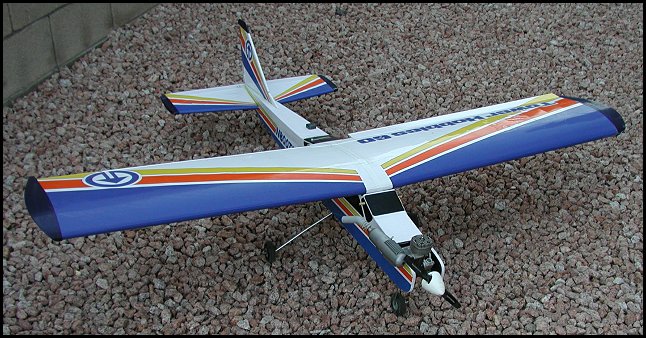 Size 060 R/C aircraft used as test platform. Documentation A project wouldn't be complete without documentation. The following is a snapshot of the work completed on the project to date. |
|
Copyright © 2001-2009, KD7LMO |
|
Web space provided by ESS, Inc. for all your consulting needs. |