|
|
Mobile GPS -
Hardware
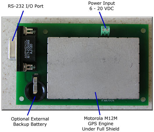
The Mobile GPS project is a small circuit board that adapts a Motorola
M12/M12+/M12M GPS engine for use in an automotive application. The design
includes reverse polarity protection, transient protection, and extended
temperature operation.

Mobile GPS Top View.

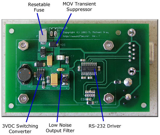
Mobile GPS Bottom View.
Theory of Operation
DC power in the range 7 to 20 volts is provided on terminal block.
Diode D1 provide reverse polarity protection. The LM2672 switching
regulator provides buck regulation down to 3.0 VDC using a high efficiency
260KHz switching frequency and small inductors. R1 and R6 set the
output voltage. C6 filters the output. Additional ripple
reduction is provided by the 4.7uH inductor and C1. LED1 provide a power on
indication. IC2 is a
standard 3VDC ST-3232 driver that provides translation between GPS 3.0 VDC
data
signals and the +/- 12 VDC RS-232C standard.
Although the Motorola GPS M12+ includes an optional internal
battery to store the GPS almanac and ephemeris data, an external battery was
utilized in this application. Since the GPS engine is mounted in the
vehicles' trunk and subject to the extreme Arizona summer temperatures an
external battery provides extended operation.
Power Converter Schematic / PCB Layout
For best quality, print the schematic on a single 8½ x 11" sheet of
paper in landscape mode using your favorite graphics application.
 |
 |
 |
Schematic
(Graphic - GIF) |
PCB
Layout
Top Layer
(Adobe PDF) |
PCB
Layout
Bottom Layer
(Adobe PDF) |
Additional information on viewing the PCB artwork, PCB tools, and
component libraries is available in the
Technology section.
|


