|
|
Servo
Driver
Shown
below is servo driver module. The module has the following design
features:
 Interfaces
to standard PWM (Pulse Width Modulation) servo motors used in R/C (Radio
Control) aircraft and cars. The servo update rate is 50Hz or a pulse
every 20mS. The pulse
width varies from 1 to 2mS to control the position of the servo motor.
A 1mS pulse moves the servo to a full CCW position, while a 2mS pulse
moves the servo to the full CW position. Interfaces
to standard PWM (Pulse Width Modulation) servo motors used in R/C (Radio
Control) aircraft and cars. The servo update rate is 50Hz or a pulse
every 20mS. The pulse
width varies from 1 to 2mS to control the position of the servo motor.
A 1mS pulse moves the servo to a full CCW position, while a 2mS pulse
moves the servo to the full CW position.
A
separate power converter handles the high surge current required by the
servo motors and avoids reset and glitch problems with the main controller.
A
high speed serial interface connects the servo driver to the main
controller.
Two
processors in the system provide a fail-safe, redundant environment.
If communications between the processors is lost, an automatic recovery
sequence will attempt to correct the problem. If a fatal fault is
detected, a parachute recovery system is deployed to allow safe recovery
of the aircraft.
Includes
interface to standard R/C receiver to allow conventional take off and
landing with manual control and automated flight once airborne.
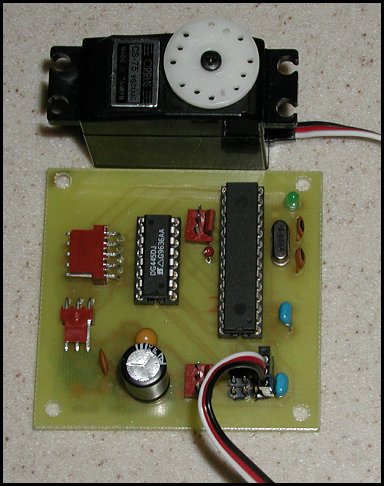
Servo Driver.
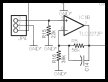
Schematic / PCB Layout
For best quality, print the schematic on a single 8½ x 11" sheet of
paper in landscape mode using your favorite graphics application.
 |
 |
Schematic
(Graphic - GIF) |
PCB
Layout
(Adobe PDF) |
Additional information on viewing the PCB artwork, PCB tools, and
component libraries is available in the
Technology section.
|