
|
|
|
|
|
|
|
Repeater Shown below is the block diagram of the cross band, voice repeater.  Cross band repeater block diagram. This is the first version of the cross band repeater board that was flown on ANSR-4 in December 2001. The board was designed to interface with the processor board that was built before the cross band repeater system. By creating separate boards, the system was built in stages to allow for testing and ease of rework. The board is a through-hole design and all the circuits reside on a 4" x 6" single side, PCB. 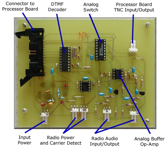 Repeater Controller - Top View. Note the "white wire" design change. To correct a design problem, traces on the PCB were cut and replaced with 30 gauge wire. After the wires are soldered, they are covered with epoxy to protect them. The entire bottom of the circuit board is sprayed with conformal coat to protect it from moisture during a flight. 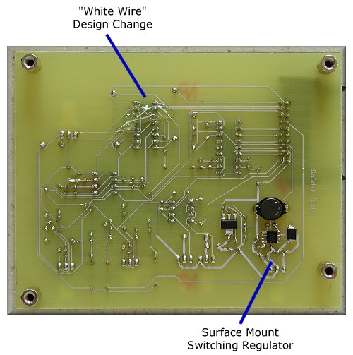 Repeater Controller - Bottom View. Repeater Control Schematic / PCB Layout For best quality, print the schematic on a single 8½ x 11" sheet of paper in landscape mode using your favorite graphics application.
|
|
Copyright © 2001-2009, KD7LMO |
|
Web space provided by ESS, Inc. for all your consulting needs. |