|
|
Controller
Shown below is the custom ATV receiver controller board.
 Embedded Controller
Microchip PIC18F252 flash memory based processor running at 3.6864MHz. Embedded Controller
Microchip PIC18F252 flash memory based processor running at 3.6864MHz.
Control LCD
Brightness Conventional potentiometer used to set the 2 x 20
contrast ratio.
RS-232
Driver TTL to RS-232 interface driver. Allows the embedded
controller to connect to external RS-232 devices.
Reverse
Polarity Diode 3 amp Schottky rectifier diode. The Schottky
diode features low drop out voltage (around 0.3 volts) even at higher
current levels.
4-Channel
DAC Used to set analog voltage for control of the video LCD
brightness, contrast, chroma level (color), and phase (tint).
PIC I/O
Extender Microchip MCP23016 Provides an additional 16-bit of
discrete I/O used to control the LCD hardware and S-band receiver. The
PIC 18F252 didn't have enough I/O to drive the 2 x 20 LCD display as well as
the other on board devices.
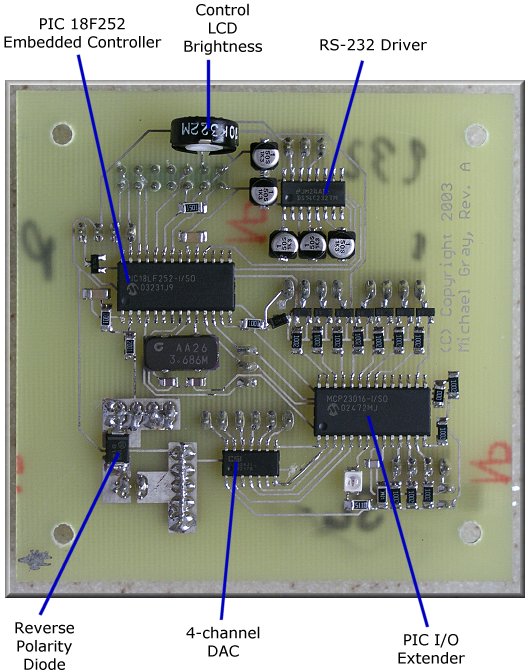
Receiver Controller Board.
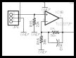
Schematic / PCB Layout
For best quality, print the schematic on a single 8½ x 11" sheet of
paper in landscape mode using your favorite graphics application.
 |
 |
Schematic
(Graphic - GIF) |
PCB
Layout
(Adobe PDF) |
Additional information on viewing the PCB artwork, PCB tools, and
component libraries is available in the
Technology section.
|